➢ High density, non-abrasive ceramic media or media mix.
➢ Two stage chemical process
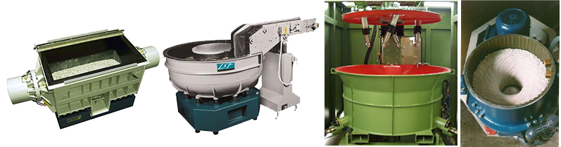
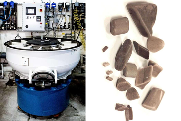
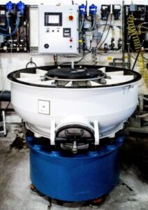
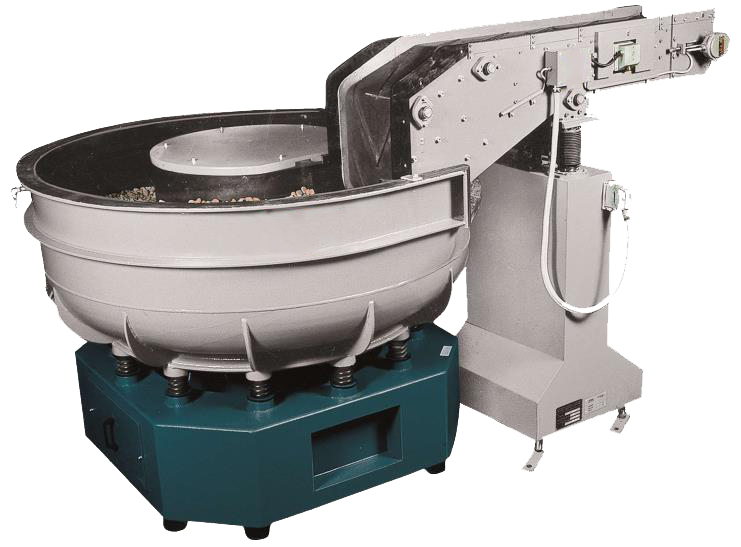
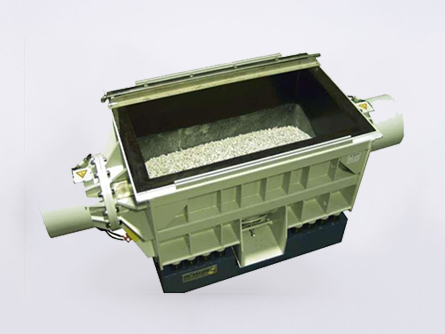
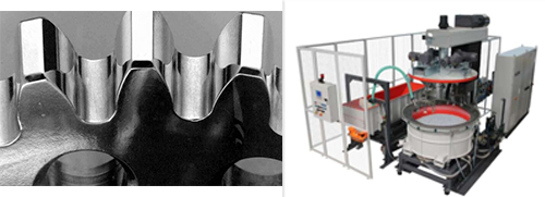
Vibratory Machine
– Creates the energy for the process
➢ Off Set weights generate centrifugal inertia
➢ Generates vibration
– Acts as reaction vessel
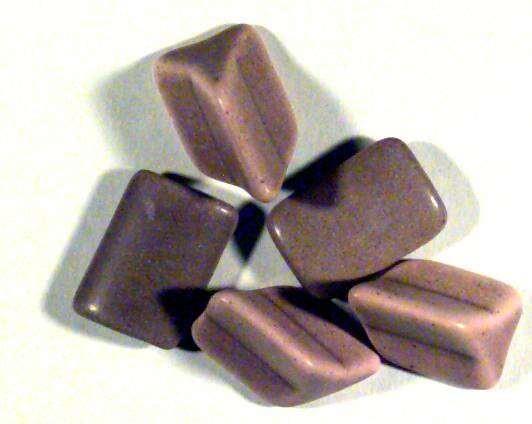
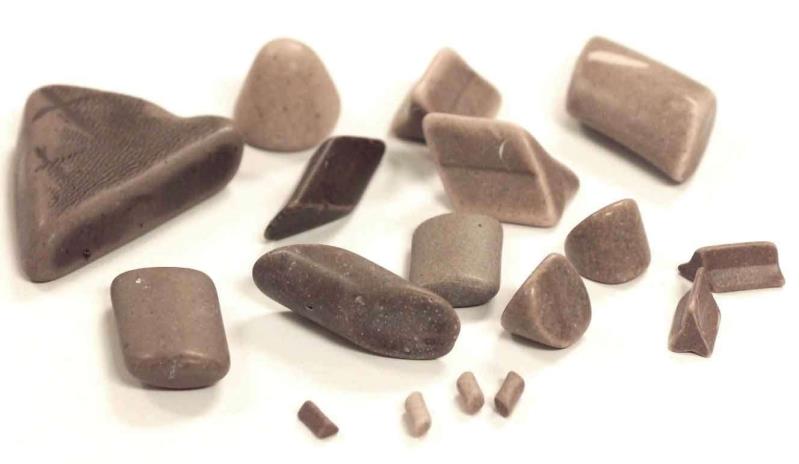
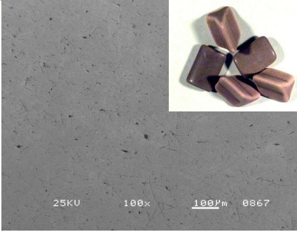
Non-Abrasive, Media
– Composition
– Off Set weights generate centrifugal inertia
➢ Aluminium Oxide
➢ Polyester Resin
– Can comprise of mixtures
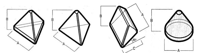
➢ Composition, size and shape
– Removes the metal.
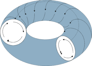
– Vibrator causes media to roll
– Media rubs over component
– Cannot remove metal without chemical!
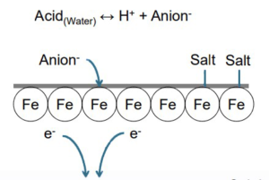
Chemical Refinement
– Weak Acids
– Acts as a catalyst
➢ Aluminium Oxide
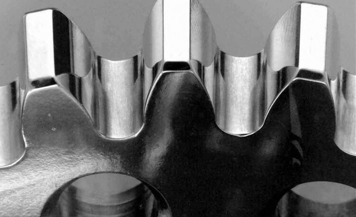
Media Motion in Bowls
Material Removal Mechanism
Salt Layer – Anion & Iron
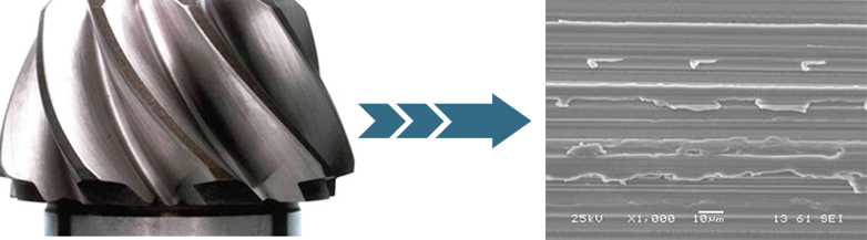
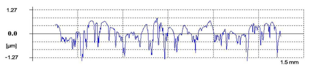
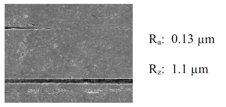
Surface as machined
Chemical reacts forming soft conversion coating on outer surface
Media removes soft coating, revealing base metal
Exposed metal reconverts and process continues
Conversion coating removed creating a bright surface finish
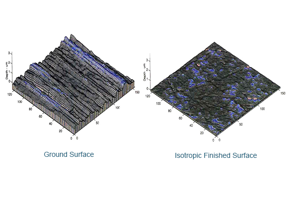
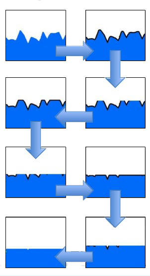
Isotropic Finishing – Process Progression
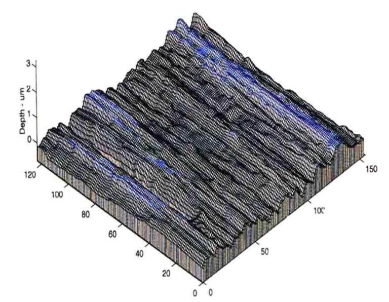
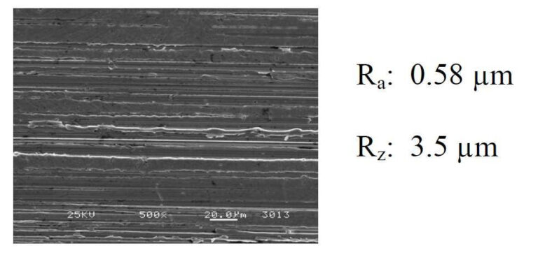
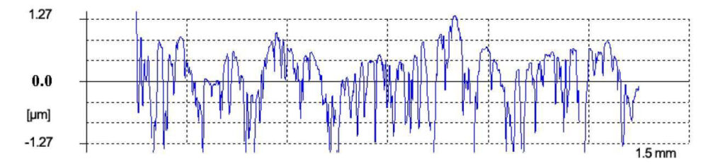
Ground Surface
– Directional Grind Lines
– Distressed Metal
– Periodic Texture
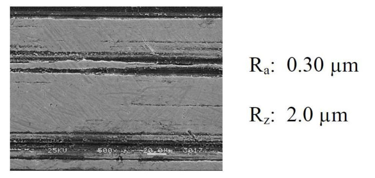
Partial Planarization
– Elimination of peak asperities
– Removal of distressed metal
– Reduction in periodic texture
Primary Planarization
– Removal of most “valleys”
– Increased “flatness”
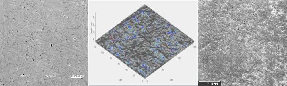
– Significant isotropic zones
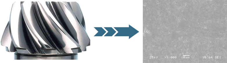
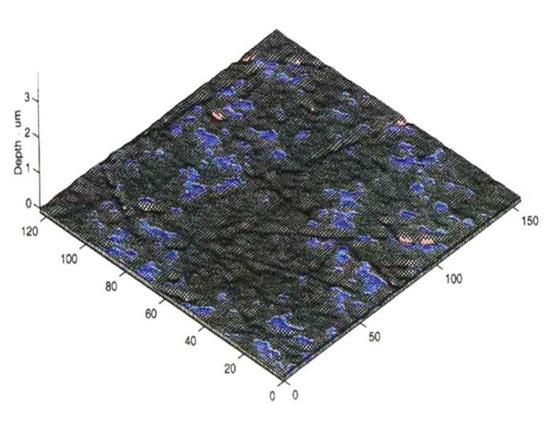
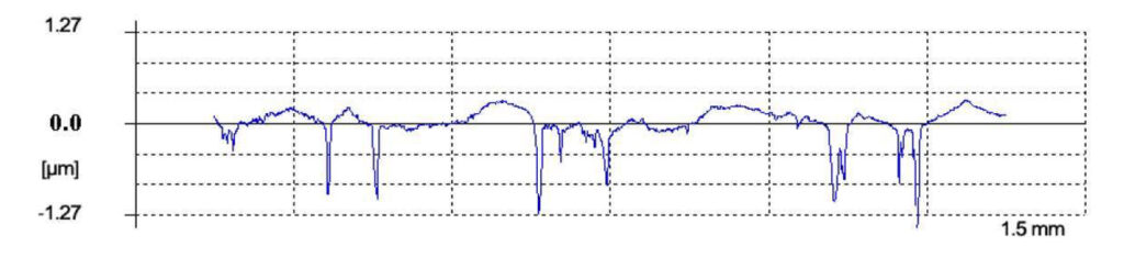
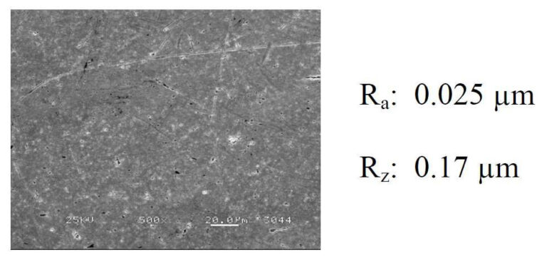
Isotropic Finish
– Removal of all “valleys”
– Complete planarization
– Fully isotropic surface
Why Perform Isotropic finishing ?
Summary of Benefits
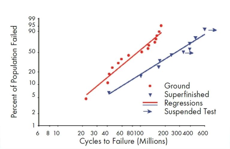
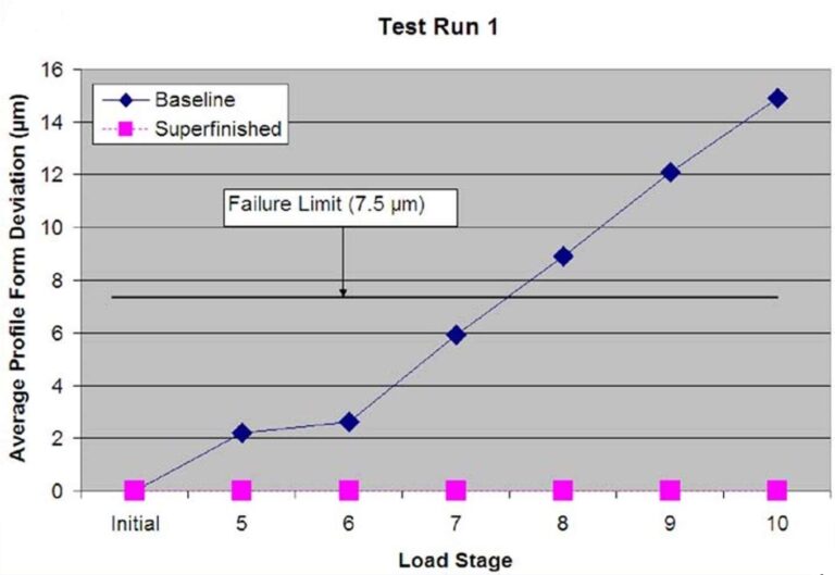
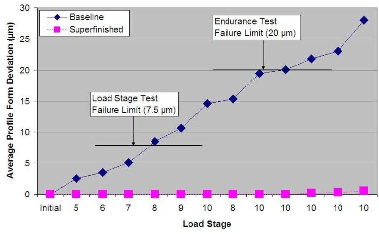
Increased Resistance to Contact Fatigue ~3x Lifecycle Increases – NASA Contact Fatigue Evaluation, X53 Spur Gears Elimination of Micropitting No Micropitting or Profile Form Deviation in FZG testing – University of Bochum Increased Scuffing Resistance ~2x applied Scuffing Load without Scuffing – Cardiff University Increased Power Density Allowable ~42% Increased Power Density Allowable – Pratt & Whitney Patent WO 2007/0646330 Reduced Friction Elimination of Initial Break-In Cycle – Falex 3 Ball on Flat Testing Increased Lubricant Performance 32 – 53° C Lubricant Temperature Reduction – Arizona Truck Technical Center, Hot Weather Testing Reduced Wear 45% reduced Iron Content in Oil post 100,000 miles – New York City Taxi Fleet Study Increased Resistance to Bending Fatigue ~5% Increase in Resistance to Bending Fatigue – University of Newcastle STBF Test Ease of Implementation Does not affect Component Geometry, Heat Treatment (including Nitriding), or Metallurgy
Chemically Accelerated: What does it mean?
Chemically Accelerated Isotropic finishing
– Utilizes “active” chemistry
➢ Generates a self-limiting, soft conversion coating
➢ Lowersrequired force to refine the surface
– Mechanism:
➢ Conversion coating is removed by non-abrasive media
➢ Conversion coating reformsin the processing appartus
➢ Surface is gently refined
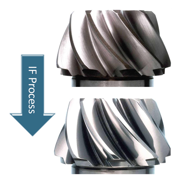
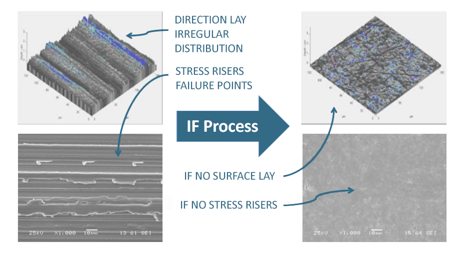
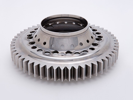
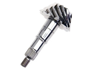
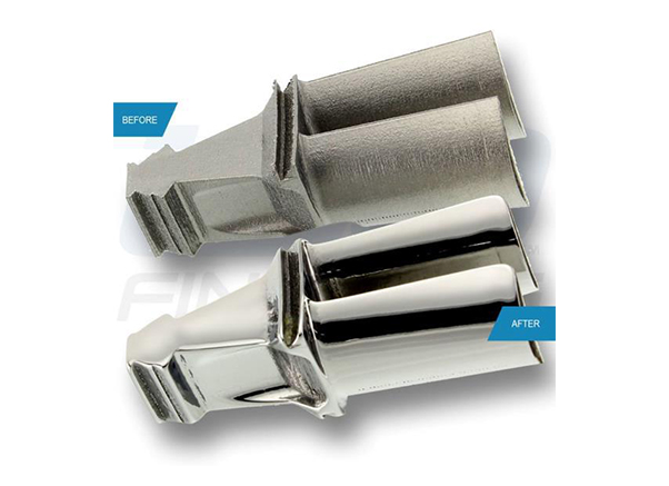
The IF Process
Micro-Textures the Surface
Maintains Component
Geometry
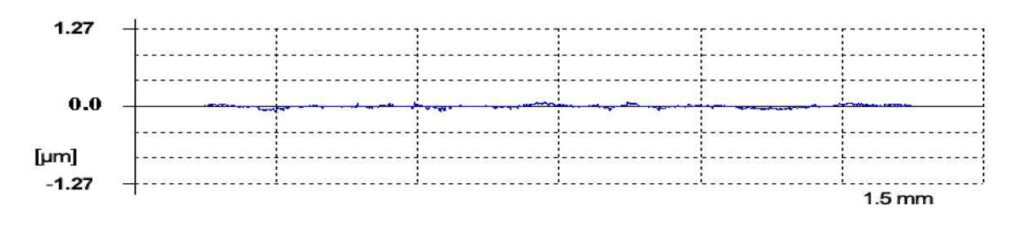
Can Produce Surface Finishes
Ra < 0.05 µm (2 µin), Rz < 0.2 µm (8 µin)
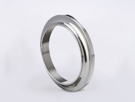
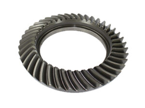
Can Process Nitrided
Components
Does Not Affect Component Metallurgy, Compressive Stress, or Hardness
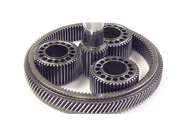
➢ Cycle Time ~2 – 4 hours ➢ Ra < 0.1 µm – Lower roughness achievable pending processing parameters ➢ Applications: – Gears, Turbine Blades, Bearings, and many more ➢ Automatable ➢ Batch Process, High Volume Capability
Rolling Sliding Contact Fatigue, Loss of Lubricant Testing
Test Specimen
Contact Stress (ksi)
Test Duration (minutes)
Result
SAE 9310H
400
30
No Failure
Ra’s = ISF <0.04 µm Specimen >30 million cycles prior to testing
Extreme Conditions: IF
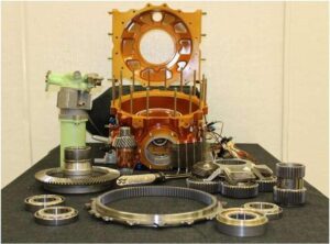
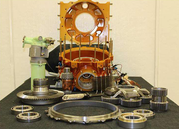
Bell Helicopter 427 Main Rotor Gearbox (MRGB)
– Low Oil Pressure ➢10 – 15 psig below specified minimum – High Temperature Testing ➢15 – 20 ⁰F above specified maximum – Both = 30 minute tests@ 550 hp & 6,000 RPM No Scoring or Contact Fatigue from Extreme Condition Testing Ra’s = ISF (Micro-Texture) 0.0381 – 0.157 µm, AverageRa = 0.091 µm
Loss of Lubricant: IF
FARDS MRGB Demonstrator Testing
– 3 gearbox designs (bearing variations) subjected to “loss-of lubricant” testing ➢ PEEK Bearing Cages ➢ Steel Bearing Cages with Heat Pipes ➢Steel Bearing Cages without Heat Pipes – ISF Process was used on all gears ➢Publicly acknowledgedat presentation
FARDS MRGB Demonstrator Testing
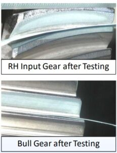
– PEEK Bearing Cages ➢ PEEK Melted at 40 minutes of operation ➢ Some signs of scuffing/discoloration ➢ Gears showed no signs of surface damage based on MPI – Steel Bearing Cages with Heat Pipes ➢ Test suspended at 73 minutes due to rapid temperature increases ➢ Evidence of scuffing, but overall gears in good condition – Steel Bearing Cages without Heat Pipes ➢ Test suspended at 85 minutes due to rapid temperature increases ➢ Evidence of scuffing, but overall gears in good condition